The RPD is no stranger to anyone who is familiar with military firearms. The rest of you have likely seen them on the nightly news in one warzone or another. For those unfamiliar, it is a belt-fed light machine gun chambered in 7.62x39mm. It was originally designed to be a squad level machine gun or Squad Automatic Weapon to go with the SKS, and later AK-47 rifles in use with the Soviet Army. It was used and produced by a number of the Communist Bloc nations. Aside from its Cold War heritage, it has been present in likely every conflict since its inception, as it has been supplied to a lot of armies and insurgent elements around the world. It was replaced in the Warsaw Pact armies by the RPK and its derivatives decades ago, but the RPD continues to soldier on in third world armies and insurgencies. I saw them frequently in my time in Iraq and Afghanistan in use on both sides.
RPDs have been in the US for some time, though the transferable full-autos are expensive enough as to be unattainable for most of us. Semi-auto variations have been on the scene here for the last 10 years or better, most recently produced by DS Arms. These are still relatively expensive. Being that I like to build my own firearms, I decided to look at building one as this also was a less expensive means of obtaining an RPD. So I started doing some research and decided that I wanted to build an RPD and that it was within my capabilities.
However, this is NOT a beginner’s level project. It involves some rather close tolerance machining operations, and some welding. You really need a milling machine and a lathe for this project. You have to convert a parts kit from a full-auto, open-bolt weapon into a closed-bolt, semi-auto configuration to legally build it. This article is not a 100% step-by-step guide to building a semi-auto RPD. It’s an overview of the process intended to give you an idea of what is required to build one (and hopefully inspire those of you with the needed skills).

I purchased the parts kit used in this build directly from DSA at the Knob Creek Machine Gun Shoot a few years back. The kit was a show special, and it came with a barrel. The RPD this kit came from was originally produced in Poland and it was in excellent shape. At present, I do not believe DSA is selling RPD parts kits. But there are other sources. Currently, Bowman Arms has RPD parts kits. Since I had been considering an RPD build for a few years before I actually bought the parts, I watched parts kits come and go for a while. It seems like every couple of years someone will bring some more in. While they don’t seem to have any more parts kits, DSA is still selling the barrels, at the time of this writing at least. I don’t believe the barrel is so complicated that it couldn’t be turned from a blank should commercially produced barrels dry up. The receiver I used for this build was also produced by DSA. At the time of this writing, they are out of stock. However, they seem to do a production run of these receivers upon occasion, and it’s still listed on their website. I have seen some folks re-weld demilled receivers. It is an option, but that process is beyond the scope of this article. For the semi-auto conversion parts, I purchased a kit from FMJ Armory. They also have detailed instructions of the whole process.
There are a number of legal considerations for an RPD build. Obviously, it needs to comply with NFA rules. Regular folks cannot legally build automatic weapons (Drat!). At no point can your build be able to function with an open bolt (which was determined by the BATFE to be a full-auto function) or be capable of firing full-auto. This build requires that you convert full-auto parts, and these parts must be additionally modified to fit into the receiver. You could end up in a bunch of trouble should you make these parts fit the receiver before you do the conversion to semi-auto. So you must give some thought as to what order to perform the work required so as to not accidentally fall into “constructive intent”. You also need to make sure that your build is 922r compliant, with no more than 10 foreign-made parts off the list. I’m not a lawyer, nor do I play one on TV. So do some research and make sure your build is compliant. At least we don’t have the 3 magazine parts to contend with in the count, as the RPD doesn’t have them (being belt-fed rather than mag-fed). Lastly, a semi-auto RPD may not be legal in your city, county, or state. Being that it does not have a magazine per se, I’m not sure how it would be viewed in states with “assault weapon bans” or magazine restrictions (Tennessee, where I reside, has neither). So make sure you know and comply with the relevant rules in your specific locality before beginning an RPD build. Now that we’ve covered all of that, onto building!
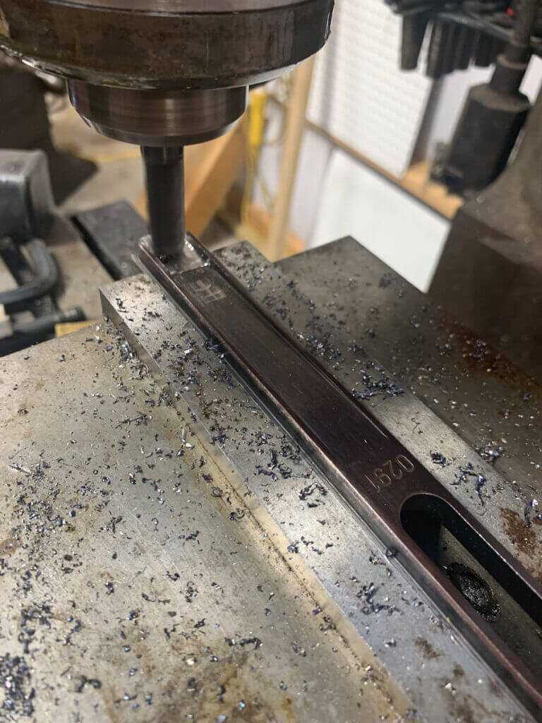
As I mentioned earlier, the receiver from DSA was designed to not allow the installation of full-auto parts. I decided to work on the bolt carrier first. In the original RPD, the bolt carrier serves several functions. A shelf on the bottom of the bolt carrier interacted with the fire control group. The front of a block on the top of the carrier hit the firing pin in the bolt as it locked into the battery, firing the round. Obviously, these features are for open-bolt, full-auto use. They must be removed for our build. It is very important that these parts are removed before modifying the bolt carrier to fit into the receiver. First, I machined off the shelf on the bottom. The carrier is fairly hard, so I used a ½” carbide endmill for this task.
The conversion parts in the FMJ kit use a striker mechanism to hit the firing pin. The design of the RPD bolt carrier requires that a transfer pin be installed in the block behind the bolt, so that the striker can actuate the firing pin. So I needed to drill a hole in the block for the transfer pin. The transfer pin is 3/16”. The hole location is quite critical. It needs to be in the right location, and it needs to be straight through the block in line with the firing pin in order for the transfer pin to hit the firing pin. This is definitely a job for a milling machine or a really good drill press.
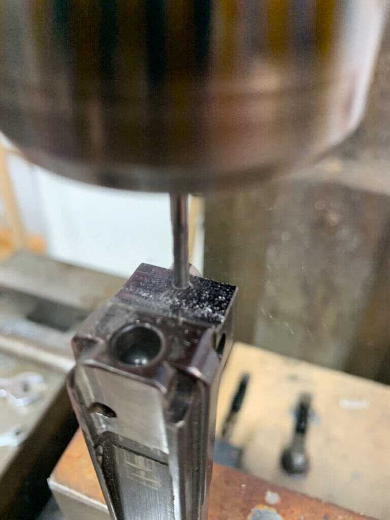
I found the instructions to be missing the location detail of this hole. I don’t know if it’s because there could be differences in the parts or if it was just an oversight. Regardless, I used the mark on the block from the firing pin as a guide. I put the hole centerline to be centered on the rear of the block, .125” down from the top. You may find you need to alter these dimensions slightly for your kit.
It is pretty tricky to set the carrier up for this with the gas piston still attached. I had a large angle plate that allowed me to do so. The carrier must be perfectly straight, both up and down as well as side to side for this operation. I checked it with an indicator to be sure, as you only get one shot at this. I decided to start by drilling a 1/8” hole so that I would still have some room to shift it if my hole location was off. As I mentioned earlier, the carrier is hardened. So, I used a carbide endmill for most of the work, starting with a 1/8”. After I drilled this hole and verified that it was in exactly the right place, I changed to a 3/16 carbide endmill and enlarged the hole. Since the pin is exactly 3/16”, it was a little bit snug. I didn’t have a .188 reamer. So, I used a #12 drill bit(which is .189”, .0015” larger than our pin) to get that last little bit of clearance. With the hole already existing, I didn’t feel like using a drill bit of proper size would be detrimental. Since this was an HSS (High Speed Steel) tool, I had to slow down considerably. But since there was only a tiny bit of material left it did the job just fine in spite of the hardened carrier. After that, the pin moved in the hole nicely, without any slop.
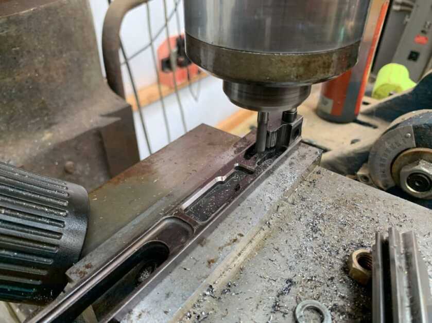
Once the hole was drilled, I needed to remove some material from the front of the block to prevent it from being able to slam fire the bolt (like it did originally). I decided to do this after drilling the transfer pin hole, so that I could use the mark from the firing pin as a reference to make sure I was putting that hole in the right place. I found that I needed to remove about .090” from the front of the block (where it contacts the bolt). Your bolt carrier may require that you remove a little more or less. You just want to remove enough material that the block can’t reach the firing pin when the bolt is all the way to the rear of its track, but not so much that the transfer pin won’t work. Again, this is a hardened part. So, I used a ¼” carbide endmill for this task.
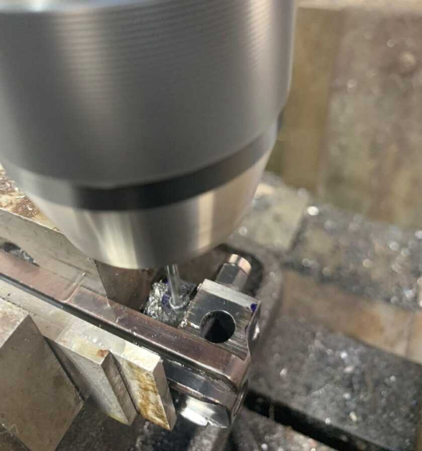
After machining the front of the block, I decided to drill the hole for the retaining pin. This retaining pin is used to keep the transfer pin from falling out. This retaining pin is 1/8” in diameter. The actual diameter of the hole is not super-critical, as you can stake the pin in place if it’s too loose. However the location is pretty important. It must be precisely located so that it fits into the slot of the transfer pin enough to retain the pin, but not so much as to cause it to bind. However, I couldn’t find anything in the instructions providing actual dimensions for this hole. After some research and measuring, I put it approximately .813” from the back of the upper part of the carrier, .245” down from the top of the block. Due to variances in dimensions of parts, you may need to alter those dimensions slightly for your parts kit. I set the carrier up in the mill, and then center drilled the hole. Again, the carrier is hardened. So I used a 1/8” carbide endmill to drill the hole.
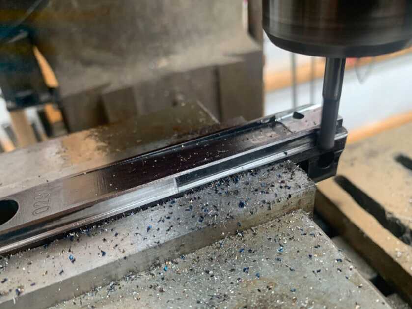
Next, the rails needed to be thinned to allow the bolt carrier to fit into the receiver. Like so many other things with this project, there is some conflicting information as to how to do this. Some sources say to remove material from the tops of the rails and others say the bottom. After some consideration, I decided to remove the material from the bottom of the rails because I didn’t want to alter the surface that the locking flaps would be riding on. The instructions call for .025” to be removed (though they aren’t particularly clear), but you may need to remove more or less depending on the size of your rails and the mating grooves in the receiver. I set the carrier up in the mill and used a ¼” carbide endmill to machine the rails. After doing this, I still found I needed to do some fitting to the carrier to get it to move smoothly in the receiver.
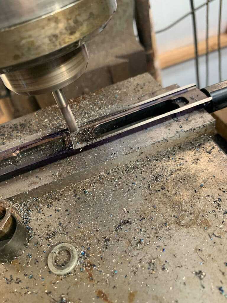
In the course of fitting the bolt carrier, I got to a point where I was not making any progress. I figured out that I needed to machine a portion of the top of the carrier down to allow it to clear the front of the receiver. The instructions provided with the semi-auto parts didn’t mention this specifically but did have some useful dimensions on the bolt carrier print. From the front of the carrier itself, I marked 3.700” inches back. I machined off .025” off of that surface. Then the carrier slid right into place.
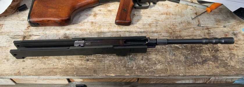
Now the bolt carrier conversion work is complete. As you can see, this is a fairly intricate process. I’ll be beginning the barrel and headspacing work in part 2.

Do you have blue prints I can follow?
Great Article. Even though light on tech aspects still gives a good look at process. I have always wanted a milling machine and a good lathe. Pipe threading machine is no lathe so I hope & save.