After the end of the Second World War, the US government supplied the former axis nation of Italy a number of M1 rifles to help rebuild their army. A few years later, NATO standardized the 7.62 NATO round, and the various armies involved began issuing new rifles chambered in it. Initially, the Italians decided to convert their existing stockpiles of M1s to the new caliber and modernize them, rather than produce whole new weapons. They machined the receivers to take a detachable magazine. Thus the BM59 was created.
In the last few years, BM59 parts kits have been available in the US. However, suitable receivers have been a sticking point for potential builders. To my knowledge, there are no receivers that are ready to use “off the shelf” currently available. Fortunately, the situation is not impossible. M1 receivers can be modified in the same fashion the Italians did. However, most of us would agree-chopping up an original M1 is something of sacrilege as they’re not exactly growing on trees these days. In a previous article, I wrote about an M1 Drill Rifle. The drill rifles are good candidates for conversion as they’re not functioning rifles anyway. In this article, I’m going to describe the machining required to convert the receiver from that drill rifle (or any other M1 receiver) into a BM59 receiver.
This is not a beginner’s project or something you can do on a drill press. You need a milling machine and the knowledge to use it properly. If you don’t have that, I would strongly suggest that you farm this work out if you want to convert a receiver. There are folks that do this work. There is no sense in ruining a good receiver.
While there are some blueprints floating around the internet, I have yet to find one that is solely for this conversion project. They all seem to be intended for completely machining a receiver (No small feat to say the least. It’s pretty easy to see why the Italians modified existing receivers), and a lot of the dimensions important for this project seem to be unreadable on the prints that I could find. I don’t think I saw any tolerances that I could actually read on the prints that I did find. Hopefully, the information I’ll provide here will shed a little light on things for those of you looking at a similar project.
You will need to use carbide tooling to perform the BM59 modifications on the M1 receiver. M1 receivers are fairly hard enough to not really be workable with high-speed steel (HSS) tooling in my estimation. That said, I still managed to get away using an HSS dovetail cutter for the stripper clip dovetail. The HSS keyway cutter I attempted to use later in this project did not work. I would recommend just using carbide tooling for both of these operations.
In doing research for this project, I have seen some people anneal the receivers prior to machining and then re-heat treat them afterward. I believe they’re doing this to allow them to use HSS tooling for the machine work. This day in age, the availability of carbide tooling makes that concept a bit ridiculous in my opinion. Not all M1 receivers used the same steel or received the same heat treatment even within American made examples (those of you interested in metallurgy may find research on that topic to be quite interesting). So I definitely recommend using carbide tooling, and NOT messing with the original heat treatment of the receiver.
I have provided the appropriate dimensions where they are relevant. But you may find that you need to do some additional fitting to get everything to go together properly when you decide to build your rifle. I would strongly recommend using layout dye and marking the dimensions on your receiver so you can see exactly what you’re doing. You will also need some BM59 parts to be able to fit to them and to figure out some of the not-so-clear dimensions. You’ll need a magazine, the front magazine catch, the bolt catch, and if you’re going to install one, a stripper clip guide. So realistically, you need the parts kit you intend to build before you begin machining the receiver.
A few remarks on some of the relevant legal stuff is in order. I am not a lawyer, so do not consider my project or remarks here to constitute legal advice. Obviously, anytime you build or modify a firearm, it needs to comply with NFA, and any other applicable laws or regulations. I reside in Tennessee, a state friendly to firearm owners. If you live in a locality hostile to the 2nd Amendment, you will likely need to take some extra steps to remain legal if it’s possible at all. So plan your project accordingly if this applies to you. If you live in a state with an “assault weapons ban”, do some real homework before beginning a project such as this one. This project involves modifying an existing receiver that was in all likelihood produced before 1960, well before the cutoff date for what is considered “pre-ban” firearms in most places. I’m not sure how this project would be viewed in that light. As such, I wouldn’t even begin the machine work I’m about to describe until you know for sure. Now that we’ve covered that, on to the machining!
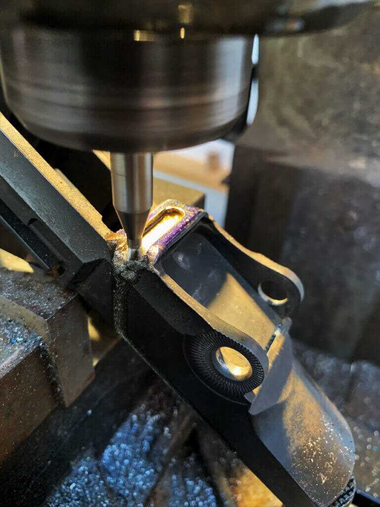
There isn’t really a particular order that this has to be done in. So the first step I took in machining the receiver was to cut the dovetail for my stripper clip guide. This is actually an optional step. You may not wish to add a stripper clip guide on your rifle, or the particular guide you choose may attach by another means. It is my understanding that some BM59 variants did not even have one. The model I wanted to build is supposed to have one, so I wanted to install one on mine. Regardless, I chose to do this first as I figured it might be a little tricky between the location of the dovetail and the angle of the feature that I needed to machine it into. As I mentioned previously, I found the carbide dovetail cutters to be quite expensive so I decided to use HSS. I decided to get an extra just in case, and I did end up needing it because I broke the first one. In light of that, I’d absolutely recommend just getting a carbide tool for this job if your guide attaches via dovetail. I roughed the dovetail out with a carbide endmill, prior to using the dovetail cutter. Again, the particular guide you use may call for a different method of attachment. So I’m not going to get into the exact details of this one.
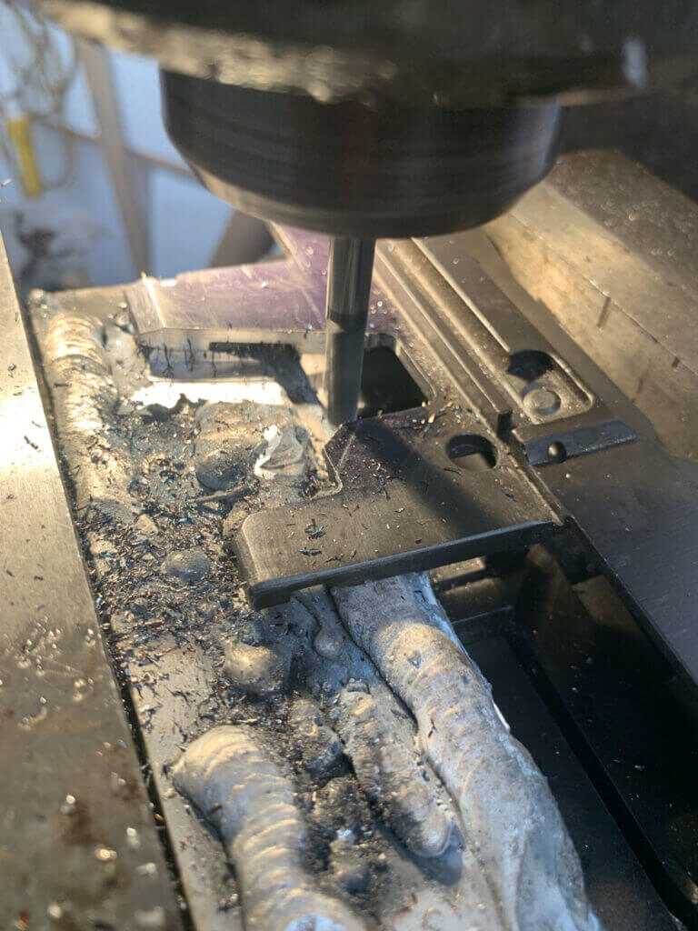
Next, I cut the angles onto the “legs” coming from the bottom of the receiver. This is necessary to allow the magazine to fit into the receiver. Since the legs really don’t have good rigidity on the ends, I stuffed a tight-fitting piece of aluminum in between the legs to help reduce the chatter. The front leg is supposed to have a 70-degree angle. The rear is supposed to be 42 degrees. I *think* these are just for clearance, so you might be able to get away with not being exact though this will likely create the need for additional fitting down the line.
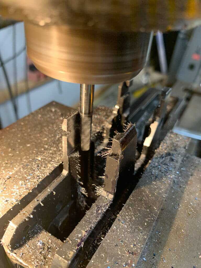
Inside the legs of the receiver are some grooves that were used for the follower assembly in the M1. These have to be removed, and the receiver opened up slightly to allow the BM59 magazine to fit. I could not find a good way to support the legs when doing this. So I used a smaller endmill (1/4”) and light cuts to reduce the tool forces and the chatter. You will need an endmill with a fairly long flute length to be able to reach everything you need to machine. The area between the receiver legs needs to be 1.025” wide from the front of the “bridge” at the back of the rear leg to the front of the rear leg. You will likely need to do some additional fitting here. I found the lack of rigidity of the legs causes some movement, and I couldn’t just “go to the numbers” and be done with it. So, I used a magazine to check my progress, removing material from “tight spots” as I went. Obviously, the magazine is supposed to fit up into the receiver until the stops on the mag prevent it from going further. It will not do this completely until the cutouts in the front are complete as well. But checking things as you go at this stage certainly won’t hurt anything.
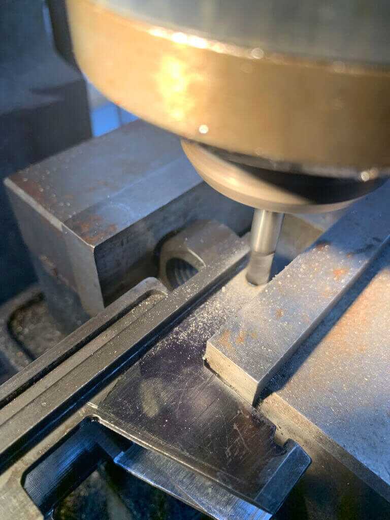
Next, I opened up the pin hole in the front. The original size is supposed to be .159”, and it needed to be opened up to .315 (8mm) for the bullet guide pin to fit. This hole needs to be pretty tight on that size to allow everything to fit properly. I believe the pin is supposed to be a press-fit into this hole. Otherwise, it looks like it could just fall out when the rifle is completely assembled. You need to find the center pretty closely, and you need to be absolutely sure that your receiver is level; otherwise, your hole will not turn out right. I used an endmill to machine the hole. I happened to have an 8mm carbide endmill-the exact size needed. I suppose you could get away with using a 5/16 carbide tool to “rough” it out, and then an appropriately sized HSS reamer for the last couple .001”s needed to get the hole to size if you didn’t have an 8mm carbide tool.
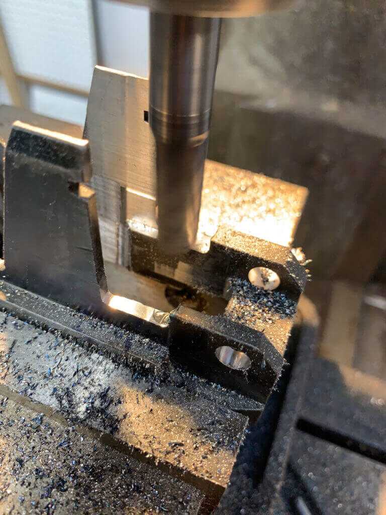
After the hole, I machined the cutouts forward of the legs. Since rigidity wasn’t as much of a concern on these cutouts, I used a ½” endmill to cut them. I didn’t want to really crank on the receiver in the vise, so I still took pretty light cuts. They need to be about .210” deep to allow the magazine to seat. The front edge is supposed to be .995” back from the front of the receiver, and the rear edge is the front of the leg. Once you are done with these cutouts, your magazine should slide all the way into the receiver. Again, you will probably have some fitting to do before it will.
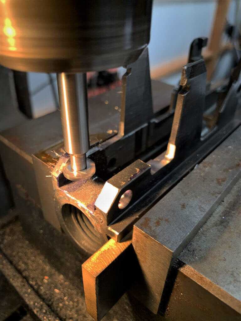
Next, it was time to cut the grooves for the front mag catch. I tried to use an HSS woodruff key cutter for this task. But, the hardened steel of the receiver ate it for lunch. So, I purchased a carbide woodruff key cutter for the job. The top of the slots are supposed to be .387” from the bottom of the “channel”. The receivers are supposed to be .102” wide. These dimensions are fairly critical. Obviously, some math is required to figure out how to touch your tool off for this task. So be careful, take your time, and double-check all of your calculations. I measured the mating part surface and came up with a slot depth of about .060”. My particular keyway cutter is .0938” thick, so I had to make more than one pass to get to the .102” slot width.
I also needed to remove some material right behind where the barrel comes in, to allow the front magazine catch to fit into place. There is a small, angled surface that must be removed for the front catch to fit. I used a ¼” carbide endmill for this task. I had to stick it out quite a bit to ensure that I could get around the receiver legs and still reach the area I needed to machine.
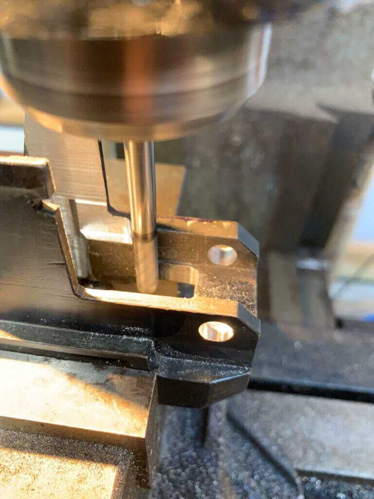
The last couple of operations all pertain to the bolt catch. A few features on the original bolt catch location have to be opened up to fit the larger BM59 bolt catch. The bottom “bar” that runs along the bottom of the bolt catch must be partially removed. The existing through slot must be widened to allow the tab on the new bolt catch to slide through. It’s supposed to be .225” wide. I used a 3/16” carbide endmill for both of these tasks. You want the back of the slot to be even with the vertical portion inside of the receiver to ensure that the tab contacts the magazine follower, rather than another place on the magazine. I also needed to slightly open up the large opening in the bolt catch area of the receiver, as that portion of the new bolt catch is slightly larger, about .010”, than the old one.
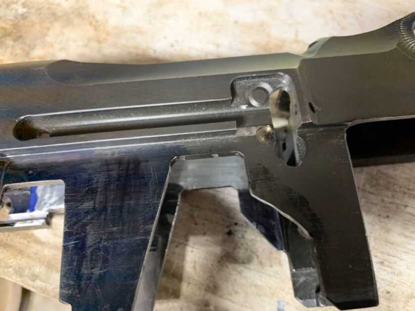
There’s also supposed to be a small blind hole for the spring added as well. However, I had no luck at all actually turning up dimensions for this. So, I used the new bolt catch to figure out as close as I could where it was supposed to go. I measured the spring, and the hole in the bolt catch itself. I decided to just go with the 3/16 carbide endmill because it was the next fractional size up from the diameter of the spring that I actually had on hand. The resulting hole is probably larger than the original, but that allows room for the inevitable misalignment that would come from how I located it. Regardless, it puts the spring where it’s supposed to be, and the catch operates properly when installed.
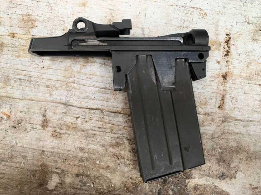
With no ready to use receivers available, modifying an M1 receiver is probably the best option to get a BM59 receiver. It is what the Italians did originally when they started making BM59 rifles. The lack of BM59 receivers currently available doesn’t leave much choice if you want to build one. If you have a milling machine and the knowledge to use it, you will find this to be a challenging and rewarding project.

Hey Chris,
Great article .! Thanks ! I have a Beretta made Danish Garand that I was considering converting to BM59E (essentially a magazine fed M1). The conversion is out of my league, so it’s great to get enough info to know that. BTW I am a retired E8 US Army. I did a tour in Iraq & Afghanistan as did two of my sons. Keep up the great work.!
Where can I have this work done? I have 2 unfinished receivers I got from Sarco. I was thinking of the front
magazine catch. Using the original pin with a .315 pin to fit between the receiver rails,and dril lit out to fit original pin.
I would be interested in the BAR / other magazine conversion to a stock M1 only., not the full BM59 conversion. Is that possible ? One could then use magazines of different capacities.
Thank you
Being a cinquanta nove fan, I found the article really detailed and machinist useful.
Being a Colorado native, I like where you went to school!
Being trained on the M1 Garand, I am particularly endeared to this “best battle instrument ever devised,” as well as probably the best caliber, the 30-06. Being a farm boy, the weight was never a problem. The only problem I could ever see was the clip and 8 round limitation. Now if you could show me how to adapt a BAR magazine, thereby keeping the 06 caliber, I would head right out to my machine shop.
I am not a machinist. I have watched a few of Ian McCollum’s Forgotten Weapons videos regarding magazine fed Garand rifles. A full auto mechanism with use of BAR magazines was experimented with in 1944, in anticipation of an invasion of Japan. The BAR magazine is not that good. Reliable functioning could not be achieved. See here: https://www.youtube.com/watch?v=_Y01YMVJrJI&t=76s I know some people have gotten BAR mags to work. You are just going to have to find a 07-FFL machinist/gunsmith to do the work. BM59 conversions in 7.62 NATO work very well.