Building My First Belt-Fed: Semi-Auto RPD Build Part 2
In part 2, I installed the barrel, components, and pinned them in place. I’ll begin this part by drilling the gas port. Before I could do that, I had to disassemble the gas block. This ended up being a little more difficult than I expected. At first, I was concerned that the parts were rusted together. However, it was just hardened cosmoline. A little heat and application of a 17mm wrench on the bolt, and I was able to disassemble it.
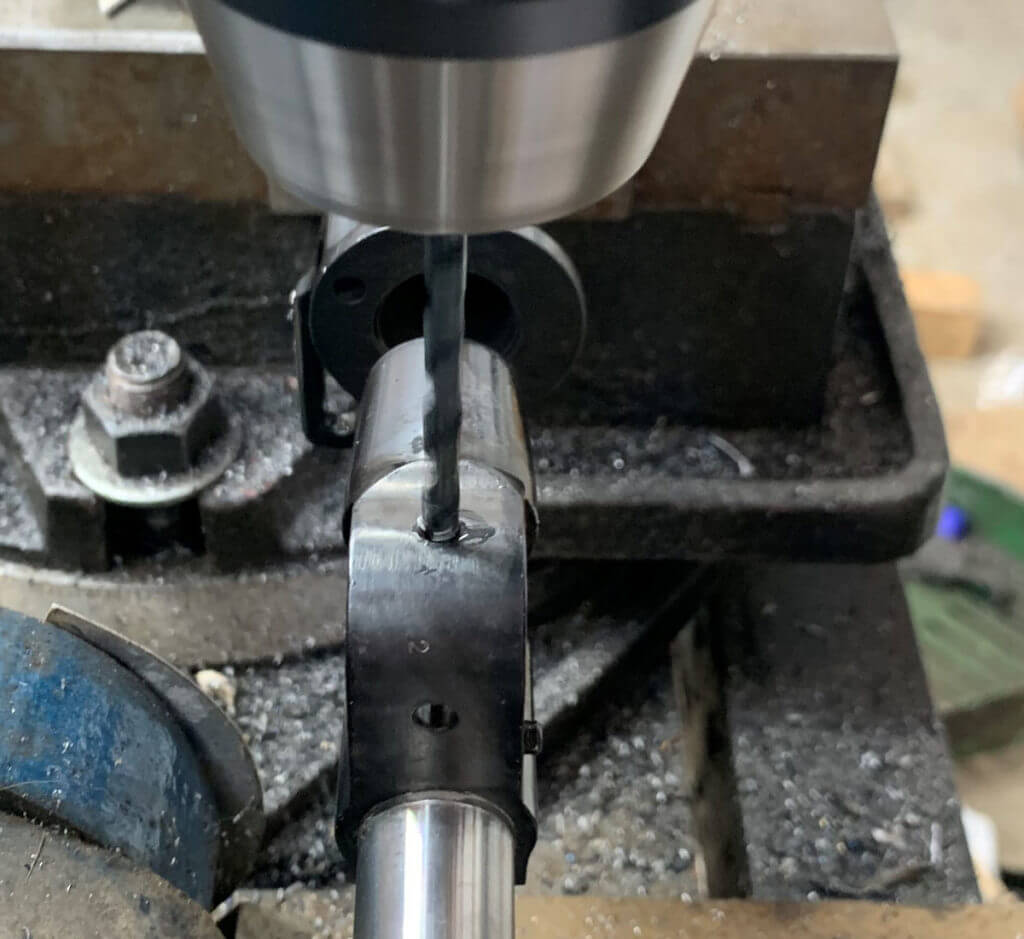
Since my parts kit didn’t have the original barrel, I had to do some research to figure out what size the port was supposed to be. For some reason, this information seemed to be rather hard to find. Eventually, I found out the port size is .174”. I used an 11/64 drill to drill the gas port, as I figured I’d start a little bit small, and if needed I could open it up. It’s not that much of an ordeal to disassemble the gas block (now that I’ve cleaned out the hardened cosmoline) to have access to the port and open it up later. Drilling a gas port into a barrel is a little bit tricky. If you just go to town on it, you run the risk of damaging the opposite side bore when you breakthrough, breaking off the drill bit in your barrel, or both. I tend to lightly “peck drill” when I’m doing something like this. As I get close to breaking through, I take lighter and lighter pecks to avoid damaging the bore by hitting the other wall. Take your time and use plenty of cutting oil.
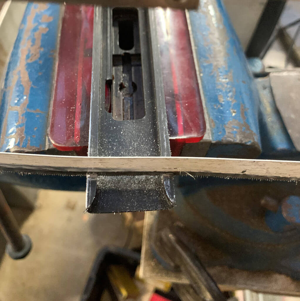
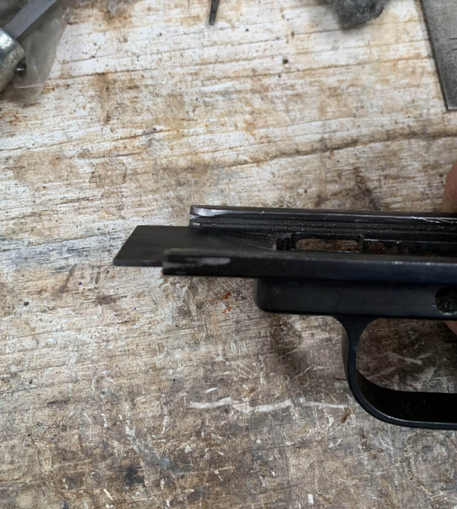
The next thing I did was to modify the lower frame to fit the semi-auto receiver. The lower receiver will not fit onto the semi-receiver in its original state. The instructions call for the rails to be removed from 5.750” from the flat where the rear of the receiver butts up to the frame. You can either just cut the whole frame off at that point, or you can just cut the rails and fit the remaining material to the receiver and not have a gap underneath when it’s all together. Mechanically speaking it really doesn’t matter, but I left the tab for aesthetics. I used a hacksaw to remove a chunk of the material. A radius is also required on the inside of the rails of the lower so that they would fit into place on the receiver. This allows the lower to go all the way forward. So then I used a file to add the radius and do the final fitting to the receiver.
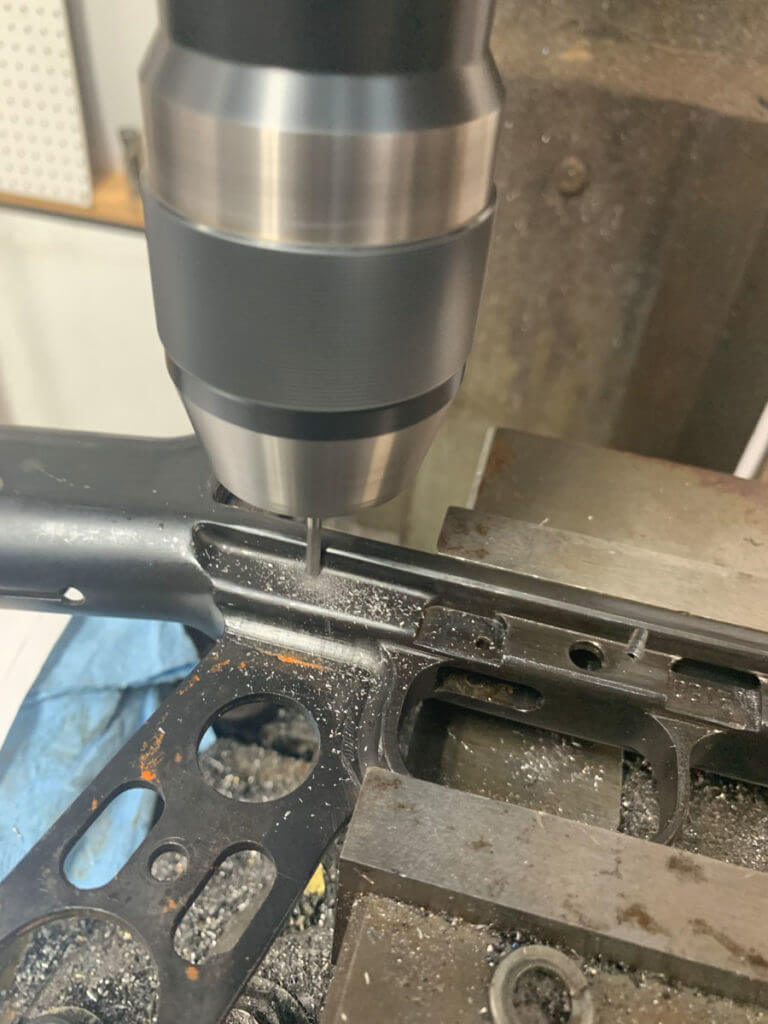
Next, the lower receiver needed the pin holes for the new fire control group drilled in it. The dimensions provided are all referenced from the trigger pin. The holes are .222” up from the trigger pin hole, with a hole 1.155” right, another 2.285” right, and one hole 1.470” to the left of the referenced hole. These locations for these holes are fairly critical, so take your time on this step. The holes are located such that they partially cut into a “wall”. So you can’t just drill them with a regular bit, as the drill bit will be forced out of position by this wall. I used an endmill to machine these holes. I machined the holes on one side and then flipped the frame over to do the holes on the other side.
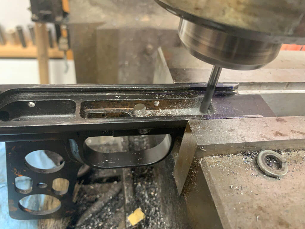
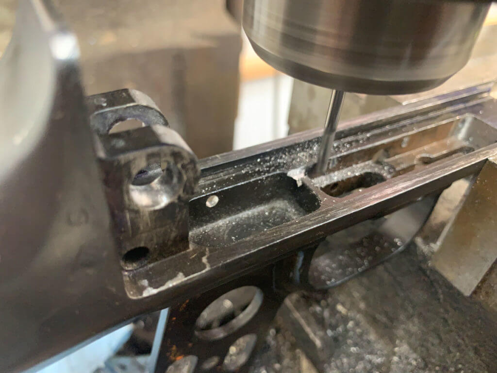
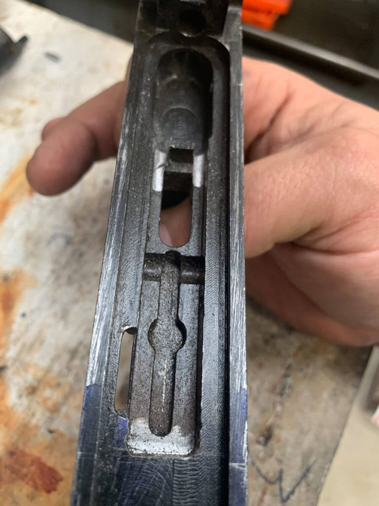
The interior of the frame has to be opened up to accommodate the new semi-auto fire control group. The “pocket” needs to be extended forward, and slots need to be machined into either side of the “web”. I used an endmill for this task. From the face, the receiver butts up to on the frame, the front of the pocket should be at 4.963” when it is complete. The two slots should be .133” wide on either side of the “web”. These features are not critical, in that they only provide clearance for the new fire control group to fit and work. So a few .001s” isn’t really going to matter so long as the parts fit properly. The center portion of the “web” needs to remain there in order for the spring to push against it as part of the semi-auto functioning.
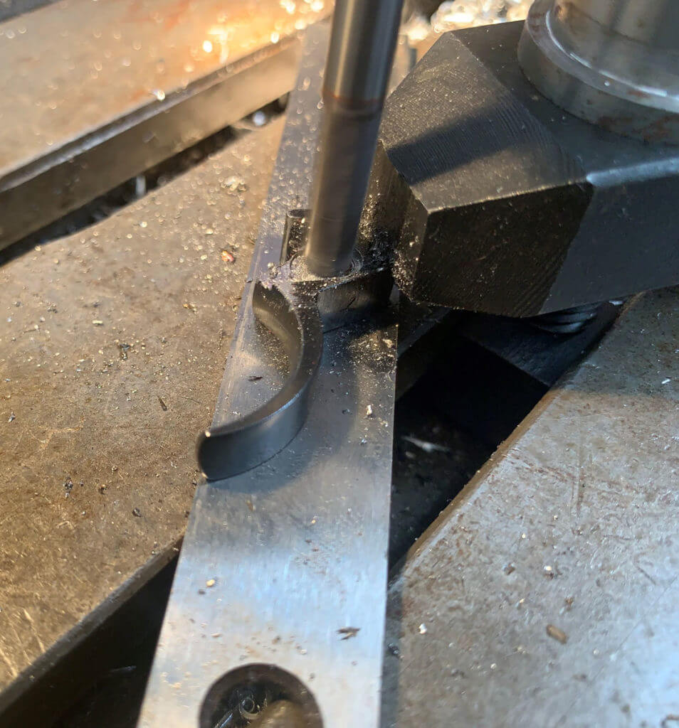
Next, I machined the trigger. This conversion uses the original trigger. But it requires some modification. It must have a slot machined into it for the new trigger return spring. Trying to hang onto such an odd-shaped item to machine it was a bit tricky. I set the trigger on a parallel and then used a toe clamp to hold it in place. I started with a ¼” endmill, centered over the trigger hole. The slot was then cut .130 deep. A secondary notch is also cut .055” deep. It’s kind of hard to describe the slot orientation, but the picture in the instructions shows it fairly well.
This semi-auto conversion also uses the original safety, again in a modified form. Because we’re changing the operation of the weapon from open bolt to closed bolt, it is necessary to add material to it. Basically, a blob of weld is added, and then shaped and fitted until the safety fits and functions properly. I found it quite difficult to do this, and I ended up doing a fair amount of additional work to the safety to get it to work after welding. I have seen it suggested that this is better done by brazing some material on the safety rather than actually welding it. Unless you are an excellent TIG welder, I would strongly suggest you go this route and save yourself some work.
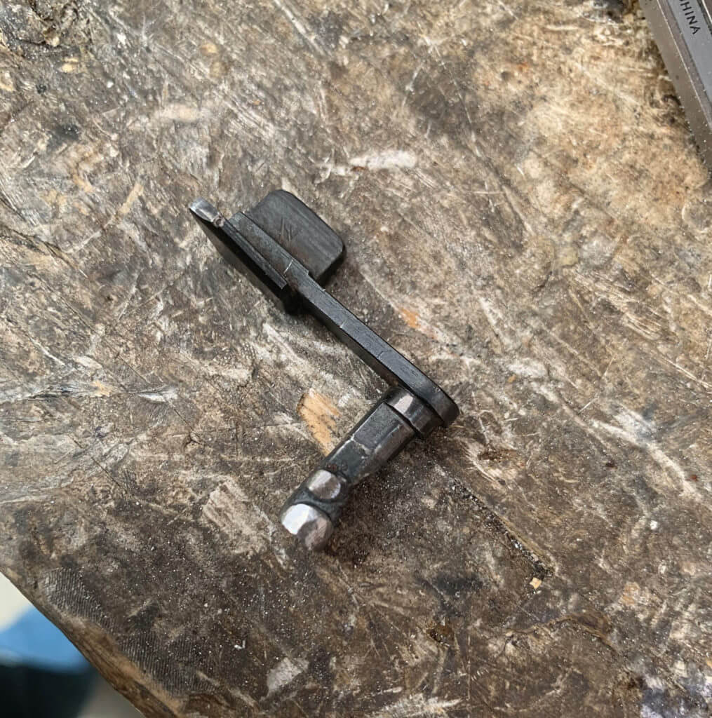
The firing pin is supposed to be removed from the bolt and modified as well. This modification is to reduce the possibility of slam fires caused by the inertia in the firing pin when the bolt closes and stops. Like the safety, a blob of the weld is supposed to be added and fitted to reduce the amount of travel the firing pin has. However, it is quite easy to warp the firing pin or melt it in half. So like the safety, I would also recommend brazing this part as well. It’s supposed to start at 1.194” back from the tip and go back about ¼”.
In the next part, I’ll fit and install the fire control group, do final assembly, and test fire the RPD. Until Next time, Happy Building!

Last year I bought the cz75 spo1 tactical sku 91153. This is the best 9mm I every shoot. I just love love it.Everyone should buy one. Great pistol. Thank you cz Charles Reber.
I am enjoying your build- keep up the excellent work!!