Read Part 1: Building My First Belt-Fed: Semi-Auto RPD Build Part 1
In part 1, I discussed the parts for the build, the legal issues, and converted the bolt carrier semi-auto. In this part, I will continue the RPD build with the barrel installation and head spacing the bolt. In researching this build, I found several different approaches to these tasks. From what I was able to ascertain, they all resulted in functioning RPDs. So there is definitely more than one way to do these operations, and what follows are the methods I chose to use.
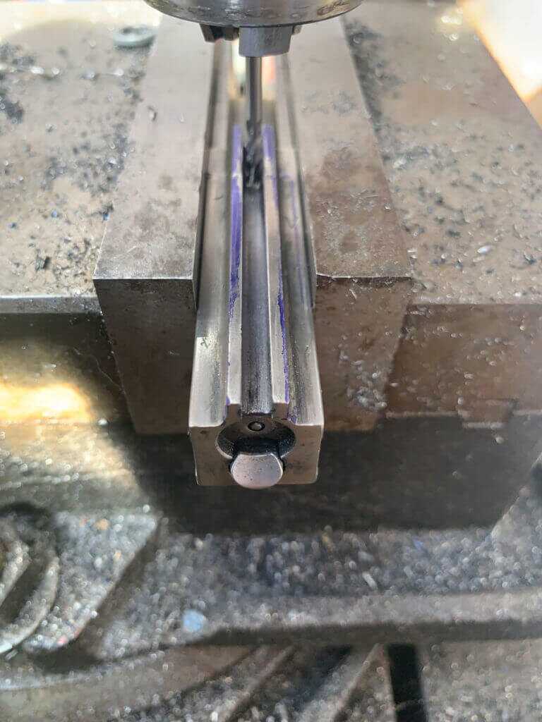
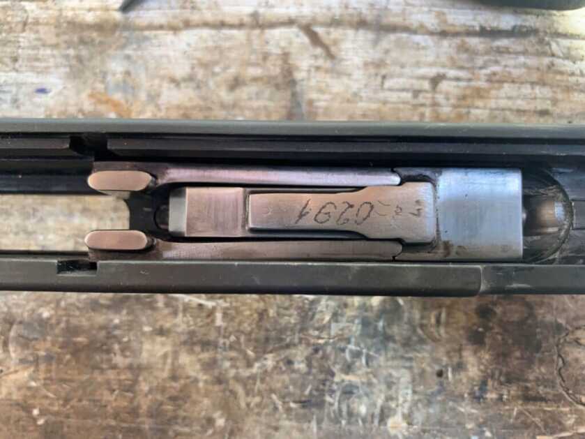
The first thing I had to do was some work on the bolt itself. With the bolt installed in the bolt carrier, it would not go all the way forward. The ejector in the semi receiver is larger than the original part. So I needed to make the slot in the top of the bolt slightly deeper, and to remove the “ramp” at the back of the slot, to allow the bolt to go all the way forward. I used a 1/8” carbide endmill for this task.
I chose to do the barrel work next. There are several critical features on the barrel that need to be sized for the parts that go on them. The barrel I used for this build is the press in type, and the receiver is intended for this type of barrel. The original RPD had a threaded in barrel. So if your build involves an original barrel (or any other barrel threaded on the chamber end) and a DSA receiver, you will have some extra machining to do before you can do the barrel installation as I’m describing here.
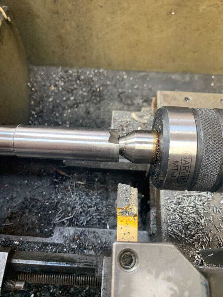
The barrel is oversized and must be turned down to match the mating bore in the receiver. Before you do this, it is very important to get good measurements of the internal diameter of the receiver bore at different depths. I used a telescoping gauge and a micrometer for this task. It may be necessary to polish this bore to even it out if it was affected by the heat-treating process. If the bore is smaller in a spot, it will greatly increase the likelihood of something going wrong when pressing the barrel in. So you really want to check the diameter in a few places to sure. After inspecting it, I did not find it necessary to polish the bore on my particular receiver.
After I determined the size of the receiver bore, I needed to turn the barrel journal to fit it. The journal on the barrel needed to be .0005”-.001” oversized from the dimensions of the receiver bore. A press-fit is necessary for the barrel to remain in place. Unlike building an AK (where you can get away with a little more interference in your fit), I could not come up with a good way to support the receiver at the point the barrel was getting pressed in. You basically have to press right on the back of the receiver and the barrel. If the barrel is too large (or the receiver bore is too small) at any point you could buckle and destroy your expensive receiver. So it is very important to get this diameter sized properly.
Before installing the barrel in the receiver, I checked the dimensions of the other journals on the barrel and compared them to the matching components. I figured it would be easier to deal with any issues at this point, rather than having to find a way to set it up in the lathe with the receiver on it later. I found differing information regarding the type of fit these parts are supposed to have on the barrel, with some sources saying that a tight slip fit is needed and others saying a press fit is needed. I assume that being the parts are pinned in place (and assuming there isn’t excessive clearance), the only one that is particularly important is the gas block. Upon inspection, I found all of the other journals on my barrel would be a light press fit into my parts. So I decided to leave those journals as they were and proceed with barrel installation.
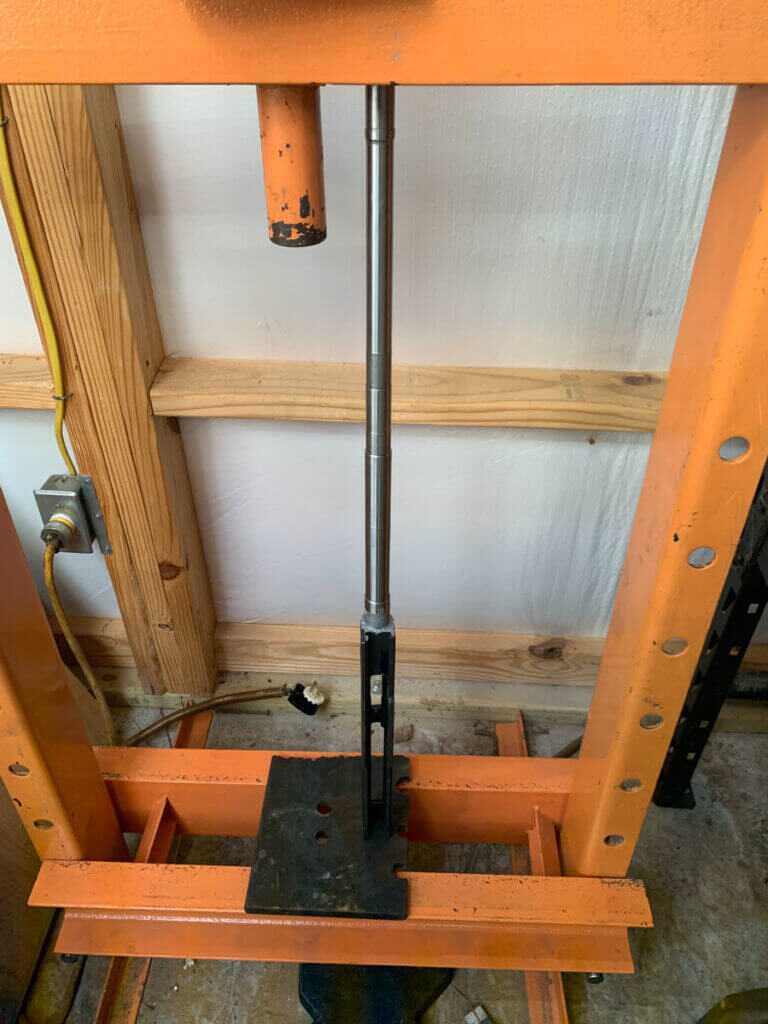
Since the barrel already had the cutout for the extractor, it needed to be properly positioned at the 6 o’clock position when I pressed it in. I always put anti-seize on press fit parts to prevent galling. When pressing in a barrel, you don’t have a lot of room between “not far enough” and “too far”. The anti-seize not only helps the barrel go in easier, but it also makes it easier to press it back out if you go too far. In attempting to set the barrel and receiver up in my hydraulic press, I ran into a problem. No matter how I tried to set it up, the barrel and receiver together were too long to fit under the ram. So I had to get creative in setting it up. Now you can see why that light press fit is so important here! I stopped short of pressing the barrel completely in to address the locking flaps.
I needed to ensure that the locking flaps actually lock the bolt in place evenly before actually setting the headspace. This process is similar in concept (but not execution) to lapping the bolt on a more conventional design. You can either do this prior to barrel installation or with barrel partially installed like I did-it doesn’t really matter. I chose to do it this way because I couldn’t come up with a consistent way to put straight pressure on the bolt. With the barrel installed, I just put the cleaning rod into the barrel and pressed on the bolt face.
A little bit of explanation on the operation of the RPD is in order so that you can understand what we’re trying to accomplish here. The RPD has a rather odd method of locking the bolt into battery. It has two locking flaps, which are separate pieces. The top “block” of the bolt carrier forces the flaps out into cutouts in the receiver to lock the bolt, and tracks on the carrier guide the flaps into place (via tabs on the bottom of the flaps) when locking and unlocking. This flap system is also how the DP28 series of Light Machine Guns. The same man designed both, so this makes sense. Because of the small contact surfaces, this system uses for locking the bolt into the battery, it is critical that both flaps have contact with the receiver when they are in the locked position. It is quite common for one flap to have a significant gap with the other fully in contact, probably due to tolerances for the locking recesses in the original receivers.
I began this process by measuring the length of the flaps. This is not an exact science because the actual contact surfaces of the flaps are at a slight angle and the front end is a radius. So there isn’t really a measurable feature that directly correlates with how the flaps contact the receiver. My thought was that if the flaps were significantly different, the overall length would be noticeably different. Conversely, if they were similar in length then theoretically they would be fairly close to what I was looking for. The flaps in my kit were identical in length. And as it turned out, they had reasonably similar contact with the receiver when locked in place.
After measuring the flaps, I marked the contact surfaces of the flaps to check the amount of receiver contact each flap had when the bolt was locked into battery. I found that the flaps were very slightly unevenly contacted with the receiver. So I very carefully removed just a little bit of material from the longer flap with a diamond needle file. Be very careful not to change the angles on the flap when you remove material, as they are critical. If you have a lot to remove, this work is probably best done on a surface grinder with a fixture to keep the proper angles. After the little bit of material I removed, the flaps had nice, even contact with the receiver.
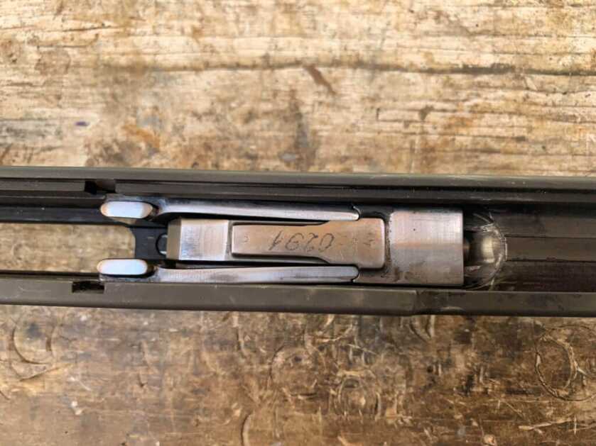
With the flaps working properly, I finished pressing the barrel into the receiver. I pressed the barrel in until the bolt would close and lock on a GO gauge, but wouldn’t on a NO-GO gauge. This isn’t very much different from building an AK. But, there is an additional thing I needed to check. The flaps are supposed to have .005” clearance when the bolt is closed on an empty chamber. I used a feeler gauge to check this. You definitely do not want the headspace on this to be tighter than it needs to be to ensure you have proper clearance.
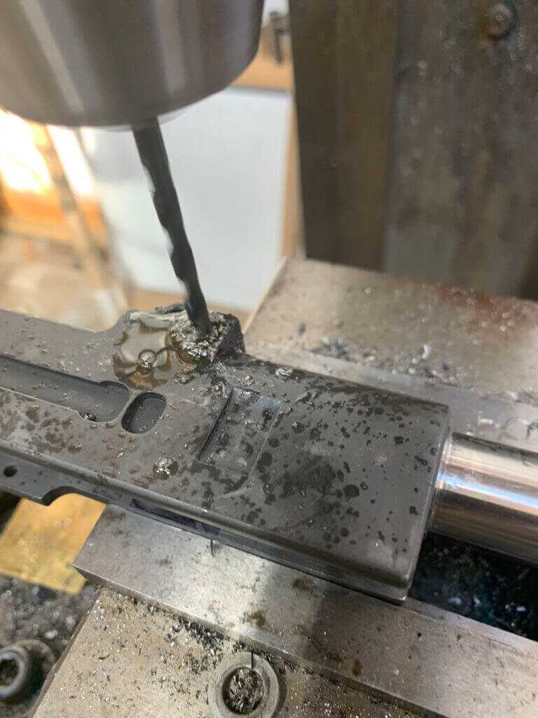
The next step is to pin the barrel into place. First, I needed to drill the hole for the pin. I spoke to someone from DS Arms about the proper pin for this purpose and was informed that 3/16 was the properly sized pin. The semi-auto conversion kit from FMJ Armory contained the pin needed for this task. I did not have the .186” reamer that would’ve been ideal. So I used a sharp #13 drill. But first I drilled the hole a size smaller, just in case it ended up oversized. I would recommend if you are going to use a drill bit for this hole that you do this as well. The DS Arms receiver has a nice little dimple where this hole is supposed to go. So it was pretty easy getting it located. I went slow and used plenty of cutting oil. My hole turned out perfectly. However, in looking at it I was a little concerned that the hole didn’t pass through the top of the barrel. The AK builds that use this type of press and pin barrel have larger pins and as such have deeper grooves cut in their barrels in this process. So, I took some measurements and did a little math (because there isn’t a direct way to measure this). Ultimately I was able to determine that my pinhole did indeed contact the barrel like it was supposed to.
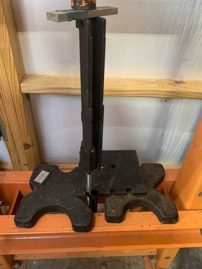
Once I had that sorted out, it was time to press the pin into place. The pin is a press fit, much like the barrel. Again, I set the barreled receiver up in the press. I put some anti-seize on the pin and pressed it in. It went in just as I’d hoped: a good press fit but not excessive.
With the barrel pinned in place, it was time to install the other barrel components. The gas piston can’t bind or drag on these so they must be properly aligned for it to pass through. After I put on each part, I made sure the gas piston wasn’t going to hang up anywhere. The gas cylinder is the first one to install. Fortunately, it does have a flat spot on the top, so I used a small bubble level to level the receiver, and then I leveled the gas cylinder. Then I used a hammer and brass punch to tap it, just to get it started where I wanted it. I checked one more time with the level to make sure it was straight. Then I pressed it onto the barrel. I found I needed to use the handguard to get it set in the right place. Then the gas cylinder support goes onto the barrel. It needs to be properly aligned to slide over the gas cylinder tube, and it also has a flat on top that helps with this purpose. It is quite possible to install this backward, so make sure it’s pointed in the right direction before you press it on and pin it.
After the cylinder support, I installed the gas block. Again, this has a flat on top that I used to align it with the level in the same manner as the other parts. If you are used to building other types of firearms, it will seem a bit odd how this is places. On a lot of RPDs, there is a sizeable gap between the gas block and gas cylinder. It is my understanding that some RPDs do not, so do not be alarmed if your build does or does not.
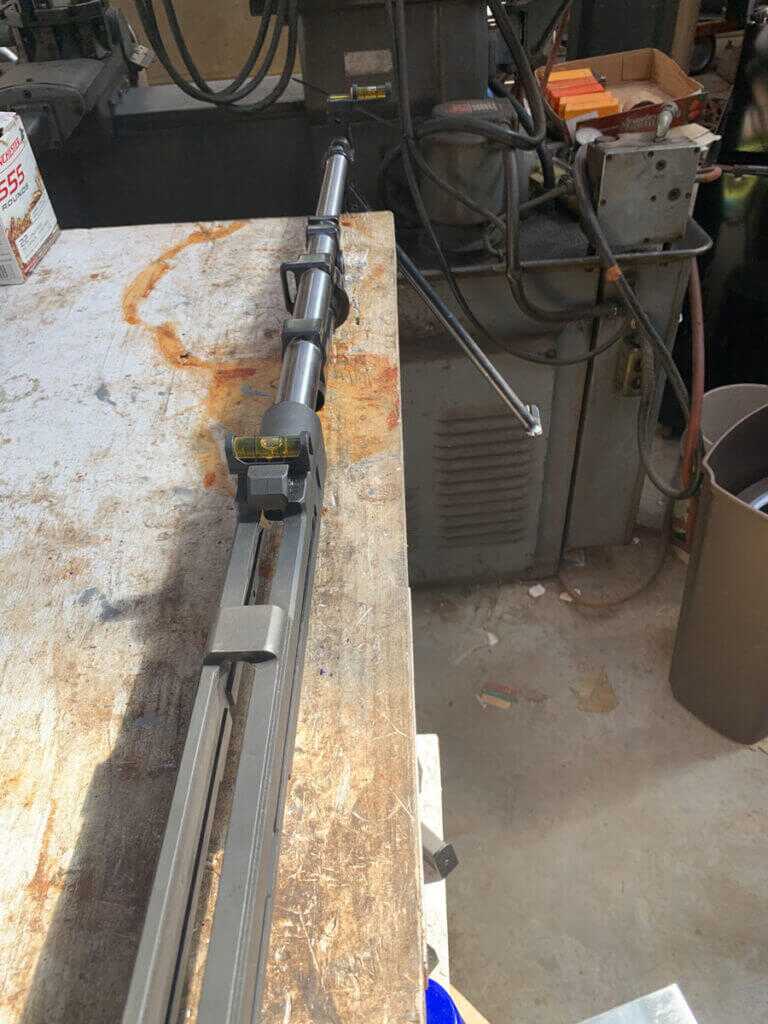
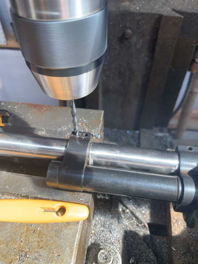
The last barrel component to install was the front sight base. Like the other components, I used a small level on either end to check alignment. While not as important for the mechanical function of the RPD, I did want to make sure my sights would be on straight. Once it was straight, I pressed it into place. With the front sight base installed, I drilled and pinned the barrel components.
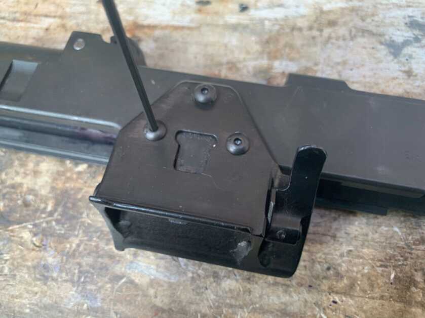
Next, I installed the drum hanger. The instructions mentioned that typically the drum hanger gets damaged during demill, and that it would need to be straightened out prior to assembly. This part was not bent or damaged in my parts kit, so I didn’t need to do this. They also mentioned countersinking the holes in it, which I believe is intended to help align the holes with the holes in the receiver. Mine lined up perfectly without any additional work. It installed with a couple of screws.
In part 3, I’ll drill the gas port, fit the feed tray components, and convert the fire control group.

As painful as it is to see an end mill held in a 3 jaw chuck, it is worse to see how much you have the cutter sticking out of the chuck. Choke up on it and you will have less cutter deflection and chatter. Just some friendly advise from a journeyman.
Give me a way to convert a semi-auto Degtyaryov DP LMG to belt fed, and I will be interested. Although having a changeable barrel would be better, the RPD didn’t have that feature either. I just can’t get interested enough to go through all that money just to be shooting the relatively puny 7.62 x 39 ammo. You might as well be shooting a heavy duty AK and be done with it. In fact it is hard to believe the commies thought this thing was a valuable asset, but then it did use the rifle round and had logistical advantages there, especially for the 3rd world countries using it, I suppose. There is no end of videos showing people shooting the full auto version until the barrel burns out – that is because they are basically worthless, and if you have a manufacturing license, you might as well have some destructive fun with them, as they are basically going to be destroyed by the BATF anyway, once your license expires. After all – what LEO would buy such a piece of junk anyway? Also – trying to find the belts for these things is darn near impossible. There are way more PKM belts available, and in fact you can probably still buy them already linked and in the metal carry box!